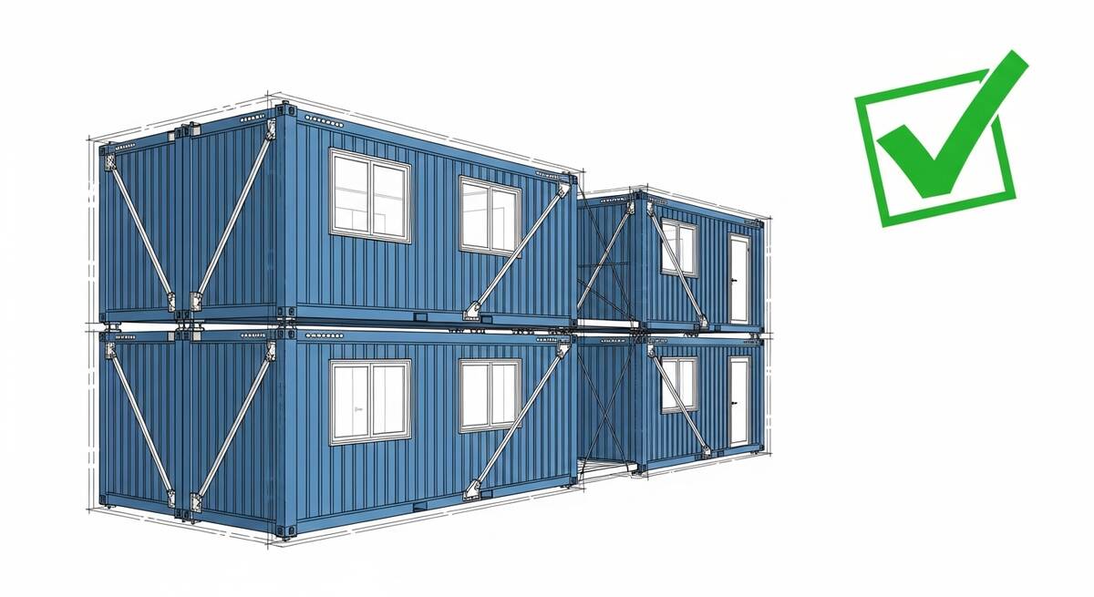
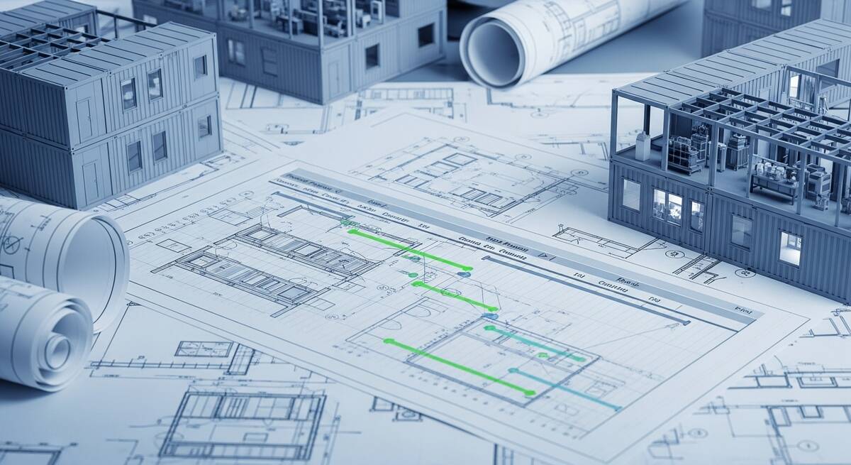
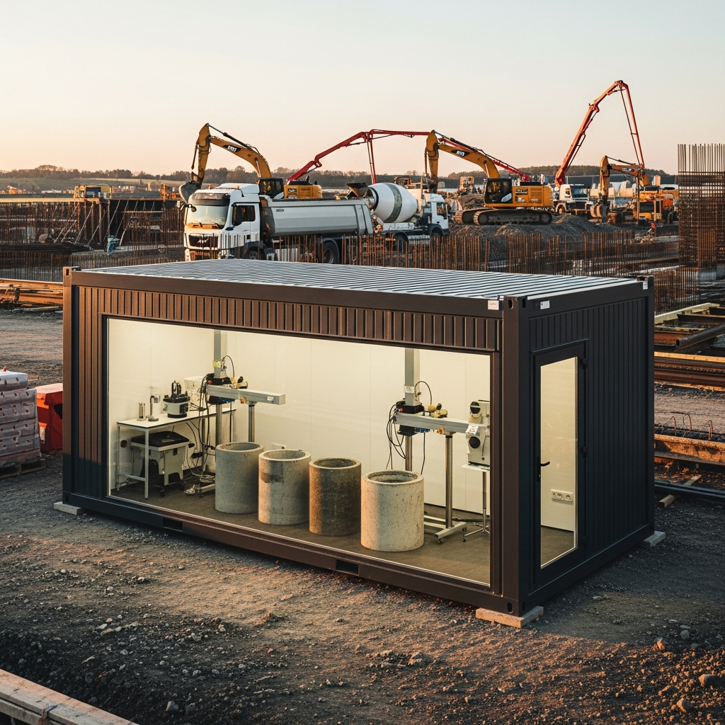
The most expensive place in a lab-container project is not the container itself, but a wrongly chosen foundation. Anyone who pours a ground slab where pad foundations would have sufficed burns four- to five-figure sums. Anyone who sets pad foundations where the ground demanded a slab risks settlements, cracks and, in the worst case, stability. The decision falls between the ground investigation and the building application – and it is a pure engineering question, not a matter of taste.
This article shows the complete chain: ground investigation, load assumptions to Eurocode, selection of the foundation variant, frost freedom, structural proof by federal state, crane and abnormal-load logistics. With verified standards, concrete example figures and an honest look at where we as container builders end and the structural engineer, the geotechnical engineer and the crane contractor begin.
Fact table: the standards that every installation rests on
Anyone who founds and installs a lab container in Germany works in a standards framework of the Eurocode family, remaining DIN standards, the state building code and accident-prevention regulations. The following overview is required reading for every building application.
| Area | Standard / requirement | What it governs |
|---|---|---|
| Basis of structural design | DIN EN 1990 (Eurocode 0) | Design situations, partial factors, limit states |
| Actions in general | DIN EN 1991-1-1 (Eurocode 1) | Self-weight, imposed loads in buildings |
| Snow load | DIN EN 1991-1-3 + National Annex DE | Five snow-load zones DE (1, 1a, 2, 2a, 3), height correction |
| Wind load | DIN EN 1991-1-4 + National Annex DE | Four wind zones DE (1 to 4), terrain categories I to IV |
| Geotechnical design | DIN EN 1997-1 (Eurocode 7) | Bearing, settlement, sliding, piles |
| Geotechnics, DE annex | DIN 1054:2021-04 | Supplementary rules to EC 7, geotechnical categories GK 1–3 |
| Ground investigation | DIN EN ISO 14688-1/-2, DIN EN ISO 22475-1 | Identification and classification, sampling |
| Soil classification, construction | DIN 18196:2011-05 | Classification for construction purposes (sand, gravel, silt, clay) |
| Earthworks | DIN 18300 (VOB Part C, 2019 edition) | Homogeneous zones (replaced the former soil classes 1–7 from VOB/C 2015) |
| Frost protection (thermal) | DIN EN ISO 13793 + regional frost maps of the state building-control authorities | Thermal design in the foundation zone, regionally valid frost depth |
| Building waterproofing | DIN 18533-1 to -3 | Waterproofing of ground-contacting elements (ground slab, strip foundation) |
| Operating cranes | DGUV Regulation 52 + DGUV Rule 100-500 Ch. 2.8 | Installation, testing, qualified operator, standing area |
| Abnormal-load transport | §29 para. 3 StVZO + RGST 1992 | Large and heavy transport (GST), escort BF3/police |
| Authorisation to submit building documents | State building code (LBO/MBO §65 ff.) | Who signs the stability proof (varies by federal state) |
| Soil protection / contaminated land | BBodSchG + BBodSchV | Precautionary duties, excavation disposal, suspected contamination |
Step 1 – Ground investigation: what lies under the container
Every serious foundation design begins with a ground investigation. What governs is DIN EN 1997-2 (Eurocode 7 Part 2 – investigation and testing) in conjunction with DIN EN ISO 22475-1 (sampling) and DIN EN ISO 14688-1/-2 (identification and classification). The report clarifies three questions: which soil is present? How load-bearing is it? Where is the groundwater?
For a standard lab container, geotechnical category GK 1 to DIN 1054 generally suffices – simple conditions, low risks, one or two boreholes or dynamic probing to 4 to 6 metres depth. On multi-storey modular assemblies, cleanroom containers on settlement-sensitive ground or known contaminated land it goes to GK 2: several investigation points, laboratory parameters (particle-size distribution to DIN 18123, Atterberg limits to DIN 18122-1, water content, density of packing), and a complete geotechnical report to EC 7.
Classification of the soil to DIN 18196 supplies the keys: sand and gravel (G, GW, GE, S, SW, SE) are generally load-bearing and low in settlement. Silt (U, UL, UM, UA) and clay (T, TL, TM, TA) are settlement-sensitive and demand greater foundation depths or a soil replacement. Organic soils (HN, HZ, F) and fill (A) are not load-bearing without special measures. With the findings the geotechnical engineer decides the foundation variant and supplies the structural engineer with the allowable bearing pressure.
Practice note: no container without an investigation
For years we have not set a container without a ground investigation – not even on supposedly “normal” inner-city sites. The extra cost of a GK 1 investigation is small in relation to the overall project. Unrecognised fill or settlement can cost a multiple of that – plus downtime. The geotechnical engineer is the cheapest insurance in the whole project.
Step 2 – Load assumptions: what the container and the environment bring
The structural engineer calculates four load groups: permanent loads (self-weight of the container including fit-out and fixed inventory), variable loads (people, mobile equipment, storage), climatic loads (snow, wind, temperature) and accidental loads (impact, earthquake in earthquake zones 2–3).
On self-weight, concrete experience helps. An empty 20-foot standard container weighs around 2.2 tonnes; a fully fitted-out lab container in 20-foot construction with furniture, ventilation, sanitary and services routing comes to 8 to 12 tonnes. A 40-foot container or a connected double module lies between 14 and 24 tonnes. These values go into the structural calculation as self-weight and are the basis for the bearing pressure.
The snow load to DIN EN 1991-1-3 with the German National Annex divides the federal territory into five zones: Zone 1 (North German Plain and parts of NRW), 1a (smaller transition areas), Zone 2 (upland foothills), 2a (eastern Bavaria and Saxony) and Zone 3 (high locations, Alpine region). The characteristic snow load at ground level (sk) begins at around 0.65 kN/m² in Zone 1 under 400 metres site height and rises markedly with height – in the Alpine foothills and the German uplands 2 to 4 kN/m² is not unusual. For a container flat roof, shape and exposure coefficients are applied; on mounted plant (ventilation unit, chiller) local snow accumulations arise that must be considered separately.
The wind load to DIN EN 1991-1-4 uses four German wind zones: Zone 1 (inland south) with characteristic basic velocity vb,0 = 22.5 m/s, Zone 2 (inland centre and north), Zone 3 (coastal proximity, northern Germany) and Zone 4 (islands and immediate North Sea and Baltic coast) with vb,0 = 30.0 m/s. For the stability of a container three wind components are relevant: the pressure component on the weather side (above all for the anchorage of the wall elements), the suction component on the roof (principal load for the roof skin and the roof anchorage), and the uplift force at container corners (decisive for the ground anchors or the self-weight balance).
The practice-relevant point: a light office container can tip or be displaced in wind zone 4 without anchorage. A fully fitted-out lab container with 10 tonnes of self-weight is generally stable against overturning, but must be anchored against horizontal displacement. Depending on the site situation we use bolting to the foundation (M16/M20 heavy-duty anchors), welding to cast-in steel plates, or on screw piles a direct bolted connection to the pile head.
Step 3 – Foundation variants: four options, one decision
The foundation variant follows from ground and load. In practice four solutions compete.
| Variant | When worthwhile | Construction time | Service life |
|---|---|---|---|
| Pad foundations | Simple 1- to 2-module containers, load-bearing soil (S, G, GW), no settlement sensitivity | 2–4 days incl. excavation and curing | 50+ years |
| Strip foundations | Standard solution for modular assemblies, medium bearing capacity, continuous load distribution under container longitudinal beams | 3–6 days | 50+ years |
| Ground slab (reinforced concrete) | Cleanroom/GMP applications, large modular assemblies, very settlement-sensitive soil, high load reserves for later stacking | 5–10 days incl. reinforcement and curing | 50+ years |
| Screw piles | Temporary installation, urgent projects, nature conservation, contaminated sites (no excavation), removable solutions | 1 day (screwing in, immediately loadable) | 25–30 years |
Pad foundations are the classic for lighter installations. Four to eight pads per container, each about 60 × 60 × 80 cm of concrete C25/30 to DIN EN 206-1, founded frost-free, with a bearing plate or anchorage for the container corners. Advantage: faster, more material-efficient and sufficient for many standard applications. Disadvantage: concentrated point loads need load-bearing soil – on silt or clay that may not suffice.
Strip foundations are our standard recommendation for modular assemblies of two or more containers. Two continuous strips of C25/30 under the container longitudinal beams, width typically 30 to 50 cm, depth 80 cm (frost-free). Advantage: even load distribution, higher stiffness against differential settlement, good connection with earthing and lightning protection. Disadvantage: more material and excavation than pad foundations.
Ground slabs of reinforced concrete (typically C25/30 or C30/37, reinforcement B500B to DIN 488, slab thickness 20–25 cm, frost skirt all round) are the premium solution. Mandatory on cleanroom containers because of vibration isolation, on GMP applications because of the settlement sensitivity of the HVAC cascade, and on modular assemblies from four modules. Bonus: the slab later also carries a stacked storey or an extension. Disadvantage: highest cost, longest construction time, largest intervention in the ground.
Screw piles – galvanised steel screws with a helical body, screwed in with a hydraulic rotary head – are the fastest option. Two to three hours per container, no excavation, no concrete, no curing. Worthwhile for temporary installations (pandemic laboratories, construction-site containers, event laboratories), for nature-conservation areas (no intervention in the soil body) and for contaminated sites (no excavation of contaminated earth, no disposal to LAGA M20 or the Substitute Building Materials Ordinance). Bearing capacity is checked by a trial borehole in advance. Disadvantage: markedly shorter service life than concrete, limited for cleanroom/GMP because of lower stiffness.
Step 4 – Frost-free founding: the invisible duty
A foundation is regarded as frost-free when it is founded deeper than the local frost-penetration depth. What governs the regionally valid minimum founding depths are the frost maps of the state building-control authorities. Thermal design of frost protection in the foundation zone is governed by DIN EN ISO 13793. In Germany a rule-of-thumb minimum founding depth of 80 centimetres applies for external elements. In the upland locations above 600 metres (Black Forest, Bavarian Forest, Ore Mountains, Harz) and in the Alpine foothills the requirement rises to 100 to 150 centimetres.
Anyone who undershoots the frost depth risks frost heave: freezing soil water expands by about 9 %, lifts the foundation unevenly and after a few winters leads to cracks, misaligned doors and, in the extreme, settlement damage to the container. Frost heave is especially a risk on cohesive soils (silt, clay) – sandy and gravelly soils are less susceptible. On screw piles frost freedom is inherent in the construction, because the load-transfer plane is automatically placed below the frost line by the screw length.
Step 5 – Structural design and building submission: who signs
The stability proof – colloquially “the structural design” – is a mandatory part of every building submission as soon as a lab container is installed permanently (generally from 3 months of standing time, depending on the state building code). Who may prepare and sign the proof is governed by the state building codes via the authorisation to submit building documents: in most federal states civil engineers, architects with a corresponding additional qualification and structural designers entered in the list of authorised persons of the chamber of engineers.
In Bavaria, Baden-Württemberg, Hesse and some further states, a checking structural design is additionally required on larger or more complex building works – a second, independent structural designer checks the calculation of the first. Whether a checking structural design is needed follows from the checking ordinances of the states and is set in the building application by building control. For standard lab containers in simple conditions it is usually dispensable; for multi-storey modular assemblies, BSL-3 containers or special buildings it is generally mandatory.
From Albstadt we supply with every container project the type structural design of the container body – i.e. the proof that the container itself takes all loads from its self-weight, wind and snow. What we cannot supply is the site-related structural design of the foundation, because that depends on the concrete ground, the installation situation and the connections. That is prepared by the local structural designer – we are happy to recommend a practice from our network.
Step 6 – Crane and abnormal load: how the container reaches the pad
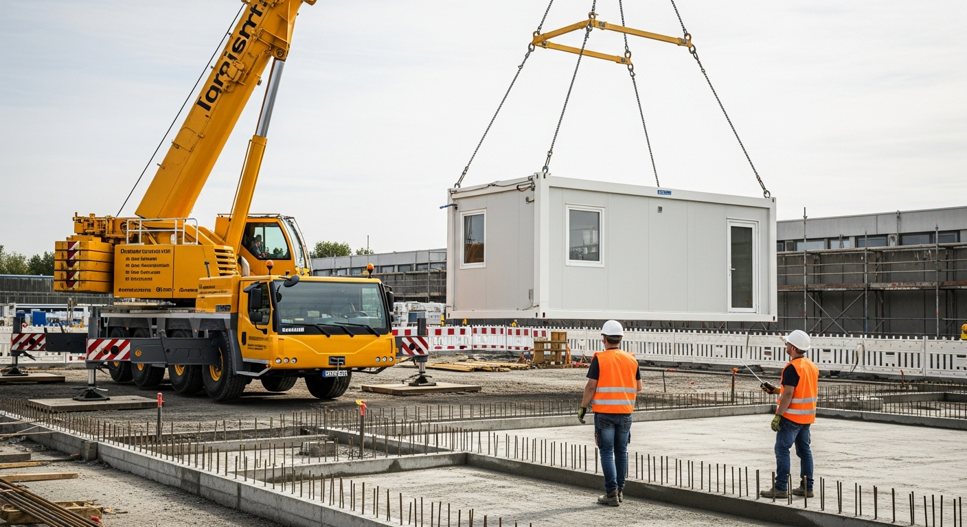
A fully fitted-out 20-foot lab container weighs 8 to 12 tonnes, a 40-foot container or a double module 14 to 24 tonnes. Installation needs a mobile crane, sized by lifting capacity and boom radius. Rule of thumb: at a short boom radius (8 m) a 50- to 70-tonner often suffices (Liebherr LTM 1050-3.1 or LTM 1070-4.2); at a medium radius (12–16 m) a 90- to 120-tonner (LTM 1090-4.2, LTM 1100-4.2). On large booms, high lift heights or over obstacles the class quickly goes to 200 to 300 tonnes (LTM 1200-5.1, LTM 1300-6.2).
What governs crane operation are DGUV Regulation 52 (cranes) and DGUV Rule 100-500 Chapter 2.8. Before installation a qualified installer must produce a lift and standing plan, check the standing area of the crane outriggers (typically 150 to 250 kN/m² under the outriggers, on very large cranes over 400 kN/m²) and organise traffic management to RSA 21. On asphalt with naturally occurring ground, crane mats under the outriggers usually suffice. On soft ground, fresh paving or over basement car parks, special constructions (additional load-distribution plates, structural proof of the basement car park) are mandatory.
Delivery is by articulated trailer – up to 2.55 m overall width, 4.00 m overall height and 40 t combination total weight without a special permit. As soon as a container becomes wider than 3.00 m, higher than 4.00 m or a combination heavier than 40 t, §29 paragraph 3 StVZO applies and the transport is a large and heavy transport (GST). Then a special permit from the road-traffic authority, escort vehicles to BF3 (federal trunk roads) or a police escort, defined routing and usually a night delivery time window become mandatory. Lead time for the permit: 4 to 8 weeks depending on the federal state.
Special situations: sloping ground, contaminated land, flooding, listed buildings
Sloping ground. At ground inclinations over 5 % the foundation must be formed stable against the downslope force. That is done with hillside formwork, retaining walls or with stepped strip foundations. The structural engineer checks stability against sliding to EC 7. Practice recommendation: over 10 % slope, a ground slab with frost skirt and slope anchors as a rule.
Contaminated land. On suspected sites the Federal Soil Protection Act (BBodSchG) and the Federal Soil Protection and Contaminated Sites Ordinance (BBodSchV) apply. Excavation must be tested for contaminants before construction (eluate and solids analysis to LAGA M20 / Substitute Building Materials Ordinance 2023); disposal follows classification into Z0 to Z2 or as landfill waste. Screw piles are often the more economic solution here, because they require no excavation.
Flood protection. In designated floodplains (HQ100) the requirements of the Federal Water Act §78 apply – buildings are only exceptionally permissible there, generally with conditions on plinth height, buoyancy securing, anchorage and electrical high-level installation. We set containers in HQ100 areas as a rule on a raised ground slab with frost skirt and define the buoyancy securing in coordination with the structural engineer and the lower water authority.
Listed buildings. On listed estates (hospital, university campus, historic works site) the lower listed-building authority is to be involved early. Frequent conditions: minimal intervention in the soil body (screw piles preferred), reversible installation, visual matching of the container cladding. Lead time for listed-building consent: 6 to 12 weeks.
Practice recommendation: which foundation for which project
From around 100 installations over recent years we distil four standard paths that carry 80 % of projects:
- 1 to 2 containers, load-bearing soil (sand, gravel), standard laboratory: pad foundations C25/30, 60 × 60 × 80 cm, four pads per container. Construction time 2 to 4 days. Most economic solution.
- 2 to 4 containers in an assembly, medium soil, standard application: strip foundations under the longitudinal beams, continuous, 30 to 50 cm wide, 80 cm deep. Construction time 3 to 6 days. Best balance between cost and safety.
- Cleanroom, GMP, BSL-3 or from 4 modules in an assembly: reinforced-concrete ground slab 20 to 25 cm, reinforced to DIN 488, with a frost skirt all round. Construction time 5 to 10 days incl. curing. Mandatory solution for regulated applications.
- Temporary, urgent, nature conservation or contaminated land: screw piles, 6 to 12 screws depending on container size. Installation on the same day. Service life adequate for 25 to 30 years.
In all four cases the rule is: the ground investigation precedes the decision, the structural engineer calculates the loads against the allowable bearing pressure, and the crane contractor checks the standing area. Anyone who skips these three steps builds either too large (money gone) or too small (risk taken on). Neither is an option in professional container construction.
Conclusion: the foundation is half of project success
A lab container only stands as well as its ground carries it. The sequence is clear: ground investigation, load assumption, foundation decision, structural proof, building application, crane concept, installation. Anyone who skips or shortens one of these stages buys risk – settlements, cracks, stability problems, in the worst case shut-downs by building control.
The good news: because our container leaves the Albstadt factory with a type structural design, defined connection points and prepared anchorages, the on-site effort can be made plannable. Our planning and engineering service covers the complete foundation design in coordination with geotechnical engineer, structural designer and crane contractor – from a single source, turnkey, with a defined chain of responsibility.
Plan the installation professionally?
We coordinate ground investigation, structural design, foundation construction and crane logistics from a single source. From the building application to handover – with verified standards and realistic time windows.
Request a free initial consultation