HVAC is the invisible life insurance of every laboratory container. It decides whether analyses are reproducible, whether staff can work safely and whether sensitive instruments function reliably. Even so, the topic is often underestimated in the planning phase – with consequences that range from inaccurate measurement results through to official conditions.
The challenge: a laboratory container is not an office container. The thermal loads from laboratory equipment, the requirements for air cleanliness and air change, the normative specifications for hazardous-substance workplaces – all of this makes the specialist technical planning of room-air technology one of the most demanding tasks in the entire project sequence.
This guide is aimed at technical directors, quality managers and planners who are preparing a laboratory-container project. It summarises the relevant standards, explains the technical relationships and provides concrete planning values – from laboratory equipment through to the maintenance strategy.
The 5 pillars of laboratory-container HVAC
Normative foundations: DIN 1946-7, TRGS 526 and further rule sets
The planning of room-air technology in laboratory containers follows a mesh of standards, technical rules and sector standards. The two central documents are DIN 1946-7 and TRGS 526 – but they are by no means the only ones.
DIN 1946-7: room-air technology in laboratories
DIN 1946-7 is the governing standard for the room-air planning of laboratory rooms in Germany. It defines minimum requirements for air volume flows, temperature, humidity and room-pressure relationships. Central specifications:
- Minimum outdoor-air rate: 25 m³/h per person, plus process-related volume flows for fume cupboards and extract systems
- Air-change rate: at least an eightfold air change per hour in laboratory rooms; with closed fume cupboards a lower rate may also be possible
- Temperature range: 20 to 26 °C, depending on room use and season
- Relative humidity: 30 to 65 % – with tighter ranges depending on laboratory type
- Room pressure: laboratory fundamentally at negative pressure relative to circulation areas (corridors, stairwells)
For laboratory containers the standard is particularly relevant because the compact construction makes compliance with air-change rates more difficult. On 20 to 60 m² of floor area, supply, extract and recirculation air must be distributed so that no short-circuit airflows arise and all workplaces are ventilated evenly. This is where the difference between a standard air-conditioning unit and a well-considered TGA concept becomes apparent.
TRGS 526: laboratories – Technical Rule for Hazardous Substances
TRGS 526 specifies the requirements of the Hazardous Substances Ordinance (GefStoffV) for laboratories. It is not an optional guide, but a binding technical rule. For the HVAC of laboratory containers the following points are decisive:
- Extraction at the point of origin: hazardous substances must be captured where they are released – typically at the fume cupboard or at the local exhaust
- Mechanical ventilation as a basic requirement: natural ventilation (windows) is not sufficient for laboratory containers with hazardous-substance workplaces
- Containment-safe extract routing: extract air from hazardous-substance areas must not enter the supply air of other rooms
- Monitoring: permanent monitoring of the volume flow at fume cupboards, with visual and acoustic alarm if the flow falls below the required value
In a laboratory container that means: the ventilation plant must be designed so that the fume cupboards, at full sash opening, maintain the required face-velocity range of 0.3 to 0.5 m/s – while simultaneously maintaining the room-air conditions. In a tight space that is a genuine planning challenge, which requires experienced specialist consultants.
Further relevant rule sets
| Rule set | Scope of application | Relevance for laboratory containers |
|---|---|---|
| DIN EN ISO 14644 | Cleanrooms and associated controlled environments | Mandatory for GMP, pharma and semiconductor laboratories |
| VDI 2083 | Cleanroom technology | Supplements ISO 14644 with German specifications |
| ASR A3.6 | Ventilation in workplaces | Basic requirement for every workplace |
| DIN EN 14175 | Fume cupboards | Sizing and testing of fume-cupboard performance |
| TRBA 100 | Biological agents | Ventilation requirements for BSL-2/BSL-3 laboratories |
| EU-GMP Annex 1 | Manufacture of sterile medicinal products | Cleanroom classes A–D with particle limit values |
| SIA 382/1 (Switzerland) | Ventilation and air-conditioning systems | Swiss counterpart to DIN 1946-7 |
| ÖNORM H 6020 (Austria) | Ventilation systems | Austrian requirements for laboratory ventilation |
Temperature control: more than merely “comfortably warm”
In an office, temperature is a comfort question. In a laboratory it is a quality parameter. Many analytical methods – from HPLC via titration through to the balance – only deliver reproducible results if the ambient temperature remains stable. The performance of a laboratory container stands or falls with temperature constancy.
Requirements by laboratory type
| Laboratory type | Temperature | Tolerance | Typical use |
|---|---|---|---|
| Standard laboratory | 20–25 °C | ± 2 K | Routine analysis, sample preparation |
| Analytical laboratory (accredited) | 20–23 °C | ± 1 K | HPLC, GC-MS, spectroscopy |
| Weighing room | 20–22 °C | ± 0.5 K | Micro-/analytical balances |
| Cleanroom (GMP) | 18–22 °C | ± 1 K | Pharma, sterility testing |
| BSL-2/BSL-3 laboratory | 20–24 °C | ± 2 K | Microbiology, virology |
| Cold room / cold store | 2–8 °C | ± 2 K | Sample storage, biosamples |
Thermal loads in the laboratory container
The cooling-load calculation for a laboratory container differs fundamentally from that for a conventional laboratory building. The compact construction and the large external wall areas relative to floor area lead to high specific heat loads. Typical heat sources:
- Laboratory equipment: a drying oven contributes 500 to 2,000 W, an HPLC system 300 to 800 W, an autoclave up to 3,000 W of internal heat load
- Lighting: 15 to 25 W/m² with LED, up to 50 W/m² with fluorescent tubes
- People: 80 to 120 W per person (sensible) for light laboratory work
- Solar radiation: up to 200 W/m² on the container envelope – particularly critical on south-facing surfaces and with a dark exterior colour
- Transmission heat: considerable despite insulation (typically 60–100 mm PU foam), because container modules have an unfavourable surface-to-volume ratio
In total, cooling capacities between 5 and 15 kW result for a typical 30 m² laboratory container – a multiple of what an office container of the same size requires. Modular construction must already take this capacity into account in the design phase.
Planning error no. 1: cooling capacity underestimated
The most common error in HVAC planning: the cooling load is calculated using office guide values (50–80 W/m²). In a laboratory with equipment, internal loads are 150 to 400 W/m². Anyone who plans too tightly here will get temperature drift in summer – and with it inaccurate measurement results.
Air-change rates: what the standards require – and what practice needs
Air change is the heart of laboratory ventilation. It supplies fresh air, carries away contaminants and keeps the room temperature stable. Requirements vary strongly by type of use – from a fourfold air change in a simple test laboratory through to a 40-fold change in an ISO class 5 cleanroom.
| Room type | Air changes / hour | Basis | Note |
|---|---|---|---|
| Office (comparison) | 2–4× | ASR A3.6 | Occupancy ventilation only |
| Standard laboratory | 8× | DIN 1946-7 | Basic requirement without fume cupboards |
| Laboratory with hazardous substances | 10–15× | TRGS 526 | Depends on fume-cupboard operation |
| BSL-2 laboratory | 10–12× | TRBA 100 | Negative pressure −15 Pa |
| BSL-3 laboratory | 12–15× | TRBA 100 | HEPA extract, negative pressure −30 Pa |
| Cleanroom ISO 7 (GMP C) | 20–40× | ISO 14644 / EU-GMP | Turbulent mixed-flow |
| Cleanroom ISO 5 (GMP A/B) | 300–600× | ISO 14644 / EU-GMP | Laminar displacement flow |
For a laboratory container with 30 m² floor area and 2.7 m room height (room volume approx. 81 m³), a tenfold air change means a volume flow of 810 m³/h. At a 15-fold air change it is already 1,215 m³/h. These volume flows must be distributed quietly, without draughts and energy-efficiently – a task that must be taken into account early in project planning.
Negative-pressure concepts: when, why and how
Room-pressure control is one of the most frequently misunderstood topics in laboratory planning. The principle is simple: a room is held at a slight negative pressure so that air always flows from “clean” into “contaminated” areas – never the reverse. In practice that means that, with the door open, air flows into the laboratory room rather than out.
Pressure cascades in the laboratory container
A well-considered negative-pressure concept works with a pressure cascade. Each area has a defined differential pressure to the neighbouring area. In a laboratory container with an airlock it typically looks like this:
Airflow follows the pressure gradient: from high to low pressure
The challenge in a laboratory container: the pressure cascade must be maintained even with the door open and with changing fume-cupboard operating states. For this, control dampers, speed-controlled fans and differential-pressure sensors are used. In BSL-2 and BSL-3 containers, automatic pressure control is even mandatory.
Practical note: leakage
A laboratory container has, by construction, more potential leak paths than a solid-built laboratory: cable penetrations, media connections, container joints on twin units. Every leak endangers pressure control. A blower-door test therefore belongs to quality assurance – ideally already in the factory, not only on site.
Filter technology: from F7 to HEPA H14
Air filtration determines what enters the laboratory room and what leaves it. The filter system is divided into supply-air filtration (protection of the laboratory against outdoor-air contaminants) and extract-air filtration (protection of the surroundings against laboratory contaminants).
Supply-air filtration
- Pre-filter G4 (ISO coarse): coarse-dust filter, protects the ventilation plant and extends the service life of the fine-dust filters
- Main stage F7 (ISO ePM1 60%): standard supply-air filter for chemical laboratories, filters fine dust and pollen
- Fine-dust stage F9 (ISO ePM1 80%): for analytical laboratories with elevated cleanliness requirements
- HEPA H13 (ISO 35 H): mandatory in cleanrooms from ISO class 7, collection efficiency 99.95 %
- HEPA H14 (ISO 45 H): for ISO class 5 cleanrooms and GMP areas class A/B, collection efficiency 99.995 %
Extract-air filtration
- Activated-carbon filter: for work with solvents, organic compounds and odorous substances – typical service life 6 to 12 months depending on loading
- HEPA H13/H14 in the extract: mandatory for BSL-3 laboratories (Biological Agents Ordinance, BioStoffV), recommended for BSL-2 depending on the risk assessment
- Activated carbon + HEPA combination: for laboratories that work with both hazardous substances and biological agents
In a GMP cleanroom container, all three stages are used: pre-filter, main stage and terminal HEPA filter directly at the ceiling outlet. Terminal filtration is decisive because it excludes contamination from the ductwork.
HVAC versus cleanroom: where is the boundary?
Not every air-conditioned laboratory container is a cleanroom – but every cleanroom is air-conditioned. The distinction is important because it has considerable effects on investment, operating costs and qualification effort.
| Criterion | Air-conditioned laboratory | Cleanroom laboratory |
|---|---|---|
| Particle control | Not specified | ISO class 5 to 8 |
| Supply-air filter | F7 to F9 | HEPA H13 / H14 |
| Air change | 8–15× | 20–600× |
| Pressure control | Negative pressure (optional) | Positive pressure (product protection) or negative pressure (personnel protection) |
| Qualification | Not required | IQ/OQ/PQ to GMP |
| Monitoring | Temperature, humidity if applicable | Particles, temperature, humidity, pressure – continuous |
| Energy consumption | Medium | High to very high |
The decision whether an air-conditioned laboratory container is sufficient or a cleanroom container is required depends on the application. For chemical routine analysis an air-conditioned laboratory is enough. For pharmaceutical production, cell-culture work or sterility testing, a cleanroom is required. Advice from Planexus clarifies this question in the needs analysis – before investment is made.
Energy efficiency: optimising 40–60 % of electricity consumption
HVAC is the largest single consumer in the laboratory container. In conventionally planned laboratories, 40 to 60 % of total energy consumption is attributable to ventilation, cooling and heating. That has a direct effect on operating costs and the CO₂ balance. For companies with sustainability goals, the energy efficiency of the ventilation plant is therefore a central lever.
Measures for energy optimisation
Heat recovery (HR)
Cross-flow or rotary heat exchangers recover 60 to 80 % of the extract-air heat. For a laboratory container with 1,000 m³/h volume flow, heat recovery saves 5 to 10 kW of heating capacity in winter. Important: for hazardous-substance extract, only a cross-flow exchanger is permissible (no mixing back into the supply air).
Demand-controlled ventilation (VAV)
Variable Air Volume systems match the air volume flow to actual use. When no fume cupboard is open, ventilation is reduced to the minimum air change. Energy saving versus constant volume: 30 to 50 %. Particularly effective in laboratories with varying occupancy.
EC fans
Electronically commutated motors (EC) are 20 to 30 % more efficient than conventional AC motors and are infinitely speed-controllable. Combined with VAV control, a clear saving results – energy consumption falls with the cube of the speed.
Night setback and standby operation
Outside working hours the air change can be reduced to the hygienic minimum. Temperature may fluctuate in a standby corridor (e.g. 16–28 °C). Prerequisite: no temperature-sensitive samples in the room and no hazardous-substance storage.
Optimise container insulation
Standard containers have 60 mm PU foam insulation. For laboratories we recommend 80 to 100 mm with thermal-bridge minimisation at bolts, frames and penetrations. The additional investment pays for itself through lower cooling capacity and lower operating costs.
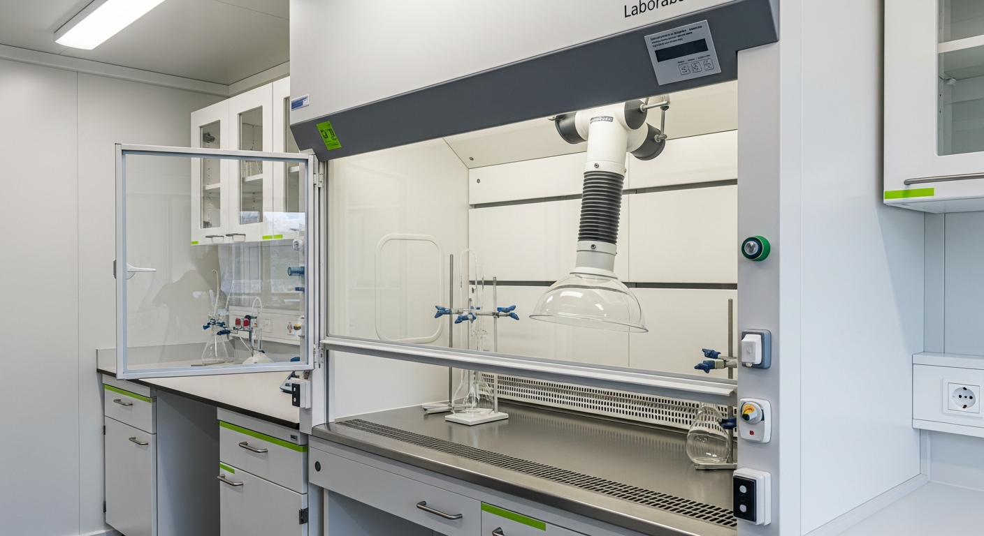
Fume cupboards in the container: sizing and integration
Fume cupboards are the primary protective devices for work with hazardous substances. In a laboratory container they place particular demands on ventilation planning because they are the largest single consumer of extract air. A single 1.20 m-wide fume cupboard requires, with the sash open, a volume flow of 600 to 900 m³/h – with a container room volume of about 80 m³ that means an 8- to 11-fold air change from the fume cupboard alone.
Face velocity to DIN EN 14175
Face velocity at the fume-cupboard sash is the central performance parameter. DIN EN 14175 and TRGS 526 require:
- Normal operation: 0.3 to 0.5 m/s at maximum opening height (typically 500 mm)
- Reduced operation: at least 0.2 m/s with the sash closed (purge air)
- Alarm: visual and acoustic alarm if the minimum volume flow is undershot
When integrating into a laboratory container, supply-air routing must be planned so that no cross-flows impair fume-cupboard performance. Supply-air outlets should lie behind the workplace so that room air flows past the person towards the fume cupboard. Details on integration can be found in our project-process guide.
Air humidity: an underestimated factor in laboratory planning
Relative humidity influences analyses, materials and corrosion protection in the laboratory. DIN 1946-7 specifies a framework of 30 to 65 % r.h. In practice the requirements are considerably tighter depending on the application:
- Standard laboratory: 40–60 % r.h. – a range that can in most cases be maintained with a good air-conditioning system
- Weighing room: 45–55 % r.h. – critical for analytical weighing with resolutions below 0.1 mg, because hygroscopic samples show mass drift with humidity fluctuations
- Cell-culture laboratory: 50–60 % r.h. – to avoid electrostatic charging and drying-out
- Electronics laboratory: 30–50 % r.h. – ESD protection with simultaneous corrosion avoidance
In a laboratory container, humidity control is more demanding than in a solid building because thermal mass is missing. The metal structure of the container does not buffer humidity. That means: every humidity change acts immediately on the room climate. For tight tolerances, active humidification and dehumidification systems are required.
Maintenance and upkeep: intervals, duties, documentation
A ventilation plant in a laboratory container is not a “set-and-forget” system. It requires regular maintenance, filter changes and performance checks. Neglected maintenance leads to falling air performance, rising energy costs and – in the worst case – to breaches of occupational-safety regulations.
| Measure | Interval | Basis | Carried out by |
|---|---|---|---|
| Visual check of filters | Monthly | VDI 6022 | Operator / building services |
| Filter change, pre-filter (G4) | 3–6 months | Differential pressure | Building services / specialist firm |
| Filter change, main stage (F7/F9) | 6–12 months | Differential pressure | Specialist firm |
| HEPA filter test (leak test) | 12 months | ISO 14644-3 | Certified tester |
| Activated-carbon filter change | 6–12 months | Breakthrough test | Specialist firm |
| Fume-cupboard inspection | 12 months | DGUV-I 213-850 | Competent person / tester |
| Refrigerant check | 12 months | F-gas Regulation | Certified refrigeration technician |
| Hygiene inspection of HVAC | 24 months | VDI 6022 | Hygiene competent person |
Logistics and installation at Planexus includes the preparation of a maintenance plan that is matched exactly to the installed components. Operators thus know from the outset which intervals apply and who is responsible.
Particularities in Switzerland and Austria
For projects in Switzerland and Austria, partly different standards and rule sets apply. The technical requirements are comparable, but the reference standards differ:
- Switzerland: SIA 382/1 replaces DIN 1946-7 as the ventilation standard. SUVA guidelines supplement employee protection. EKAS guidelines regulate the handling of hazardous substances. For GMP applications the same EU specifications (Annex 1) apply, because Switzerland has a Mutual Recognition Agreement (MRA) with the EU.
- Austria: ÖNORM H 6020 regulates ventilation systems. The ArbeitnehmerInnenschutzgesetz (ASchG, Employee Protection Act) and the Grenzwerteverordnung (GKV, Limit Values Ordinance) replace TRGS 526. The OIB guidelines define fire-protection requirements for ventilation. For accredited laboratories, ÖNORM EN ISO 17025 applies.
Planexus plans and supplies laboratory containers for the entire DACH region. We know the local standard differences and already take them into account in the specialist planning phase. That way you avoid surprises at acceptance.
Worked example: HVAC concept for a 40-foot chemistry laboratory container
To make the theory tangible, we walk through the HVAC planning for a typical laboratory container: a 40-foot module (approx. 30 m²) for chemical analysis with one fume cupboard, an HPLC system and a drying oven.
Planning data
Floor area
30 m² (12.0 × 2.5 m net)
Room height
2.7 m clear
Room volume
81 m³
Workplaces
2 people
Internal heat load (equipment)
approx. 3,500 W
Fume cupboard 1.20 m wide
750 m³/h extract
Total air quantity (10× AC)
810 m³/h
Cooling capacity (calculated)
8.5 kW
Heating capacity
4 kW (electric)
Pressure control
−15 Pa (negative pressure)
In this example the fume cupboard dominates the air quantity: 750 of 810 m³/h is attributable to the fume cupboard alone. The remaining 60 m³/h covers occupancy ventilation. Supply air is blown in via ceiling outlets in the rear of the container, flows past the workplaces and is extracted at the fume cupboard and via a transfer to extract. The cooling plant – a split air-conditioning unit with 10 kW cooling capacity – pre-cools the supply air to 16 °C before it enters the room.
Smart Lab: digital monitoring of HVAC
Modern laboratory containers rely on digital monitoring and control systems that capture all climate-relevant parameters in real time. A Smart Lab integration enables:
- Real-time monitoring: temperature, humidity, pressure and volume flow on a dashboard – locally and remotely
- Automatic alerting: limit-value exceedances are reported immediately by e-mail or SMS
- Historical data: trend display and evaluation for quality management and audits
- Predictive maintenance: filter service-life prediction based on differential-pressure trends – filter change before performance drops
- GMP-compliant data logging: tamper-proof recording to 21 CFR Part 11 / EU-GMP Annex 11
Especially in laboratory containers that are often operated decentrally or at changing locations, remote monitoring is a decisive advantage. Operators can check climate values at any time without having to be on site – and for mobile laboratory solutions that is particularly important.
Checklist: planning HVAC correctly
The following checklist summarises which points must be clarified in the planning phase. It serves as a basis for discussion at the first meeting with the TGA planner.
Planning checklist – HVAC
Conclusion: HVAC is not comfort – it is the foundation
The HVAC of a laboratory container is not a comfort question. It is a basic technical requirement that decides the usability of the entire laboratory. Anyone who saves here saves in the wrong place – because inaccurate measurement results, staff health and official conditions later cost a multiple of the planning effort saved.
The good news: with the right planning, a laboratory container is able to achieve the same HVAC standards as a conventional laboratory building – at a considerably shorter realisation time and with greater flexibility. What is decisive is that TGA specialist planning is integrated into the project process from the outset – not as a subsequent appendix, but as a parallel planning strand.
Planexus takes on the complete HVAC planning for laboratory containers: from the needs analysis via the cooling-load calculation through to commissioning and documentation. We plan to DIN 1946-7, TRGS 526 and the relevant sector standards in each case – for the entire DACH region.
HVAC concept for your laboratory container?
We prepare an individual ventilation and HVAC concept for your laboratory-container project – including cooling-load calculation, filter selection and maintenance plan.
Book a consultation now